The Box
Here one can find documentation re: the GReX box, including cables, routing, etc. A 3D PDF is available for download here. The BOM is available here
Interface Plate
The custom interface plate is machined from stock aluminum measuring approximately 12x3x1/8 inches. The drilled hole specifications are shown in the drawing below:
| Interface Plate Drawing |
|---|
 |
Tips for machining
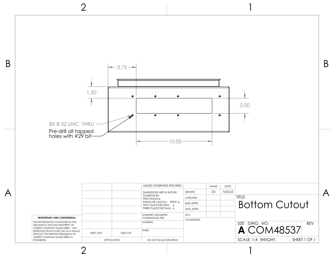
The drilled holes are measured such that the stock size does not need to be precise. This plate will later be used to mark the corresponding holes on the main box, so the outer eight holes could be measured from all four sides. We assume the long edges arrive machined parallel. Note that the eight tapped holes around the perimeter of the piece should first be drilled with a #29 bit. After aligning the plate and marking the bottom of the box, the holes are re-drilled using the specified #18 bit.To adhere the interface plate to the main box, first the cutout must be made with a jig saw. Refer to the drawing below for placement. Note that the "bottom" of the box is defined when the lid is facing upwards and the hinge is on the left side. Double check that the internal ground pin is not removed or damaged with the cutout.
| Box Cutout Drawing |
|---|
 |
Tips for machining
After marking the box according to the above drawing, we marked four points: one inside each corner of the cutout, offset 3/8" from the edge. We drilled 3/4" holes at each point, which served as entry points for the jigsaw blade (20 TPI, no oscillation). File generously to remove sharp edges.After the cutout is finished, use the interface plate to mark the location of the eight screw holes. When determining the position of the interface plate, ensure that there is sufficient clearance space for the locking washer on the nipple pipe.
After making the bottom cutout, all external surfaces of the box are painted white.
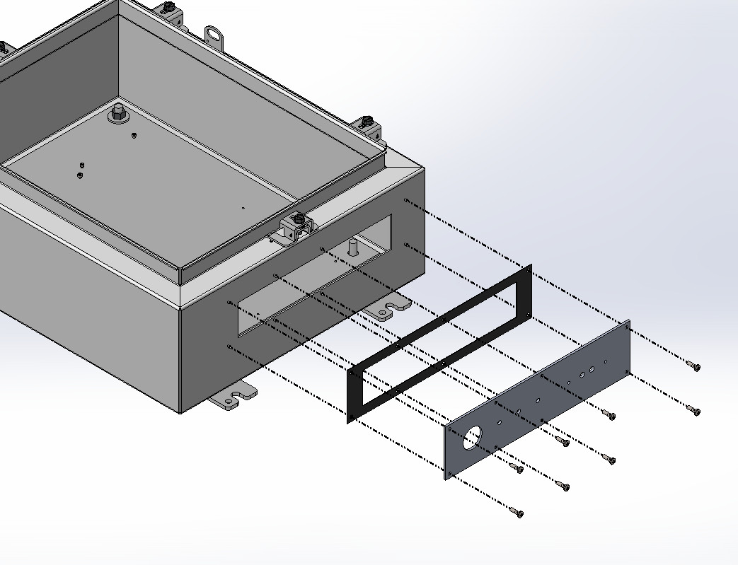
Affix the interface plate and conductive rubber gasket to the box with pan head cross screws, #8-32 5/16", containing a rubber O-ring.
| Interface Plate Assembly |
|---|
 |
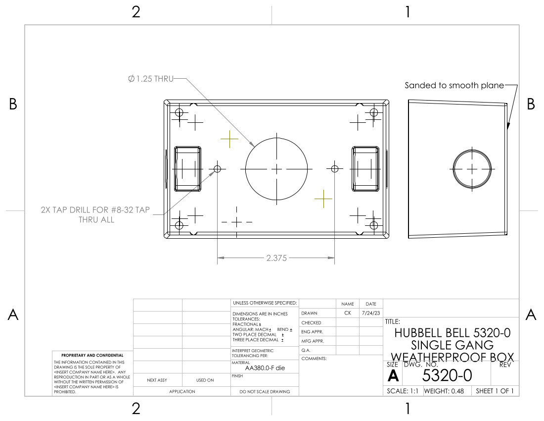
Grind down the back cover of the weatherproof box so that it lays flat against the interface plate. Drill the center hole with the step drill and the clearance holes for the 8-32 screws. Alignment is not critical, as long as the center feedthrough connectors are within the center hole, and the distance between the outer tapped holes matches with their distance on the interface plate.
| Weatherbox Modifications |
|---|
 |
Note the location of the green ground pin when the weather box is affixed to the interface plate. Use the provided plugs to close both side holes.
Punch out the center hole and corresponding screw holes from the provided foam weatherbox gasket. Be sure to thread the extension cord wire through the lid and gasket prior to soldering the wires to the feedthroughs. Close both weatherbox lid side holes with the provided plugs.
| Weatherbox Assembly |
|---|
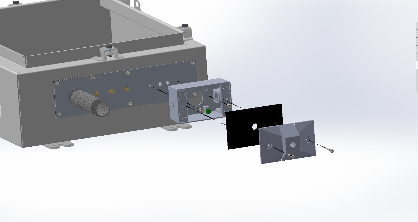 |
The 1in diameter pipe is secured on both sides by a locking washer (not pictured). The three SMAs are secured with one nut outside, one locking washer and two nuts inside.
Trim the foam gasket flush to the weatherbox, and the conductive gasket flush to the interface plate. Using RTV108 translucent adhesive, seal the following edges: between the weatherbox lid and body, around all plugs in the weatherbox, around the outside of the interface plate, and around the outer locking washer of the 1in nipple pipe.
Enclosure Plate
The steel plate that comes provided with the enclosure box is discarded and replaced instead with an aluminum plate. Use a step drill for the four corner post holes. Drill the chassis holes on the bottom layer of the FEM assembly so that they fit 4-40 hardware. For the SNAP and GPS boards which are attached with standoffs, the screw length to affix the board to the standoff is 3/16" and to affix the standoffs to the plate the length is 1/4".
| Enclosure Plate Drawing |
|---|
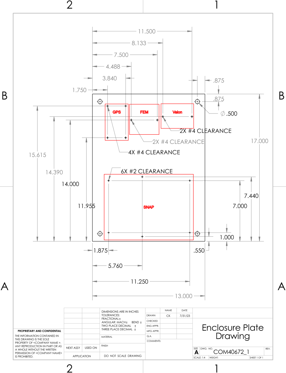 |
After affixing the FEM, screw the MiniCircuits amplifiers to the SMA connectors to determine how high they sit off the plate. Fill the gap with 2-56 size washers (should be around 3). Drill the 2-56 clearance holes for the amplifiers with them in place. Choose appropriate screw length, will vary if many more or less than 3 washers used.
Enclosure Lid
| Enclosure Lid Drawing |
|---|
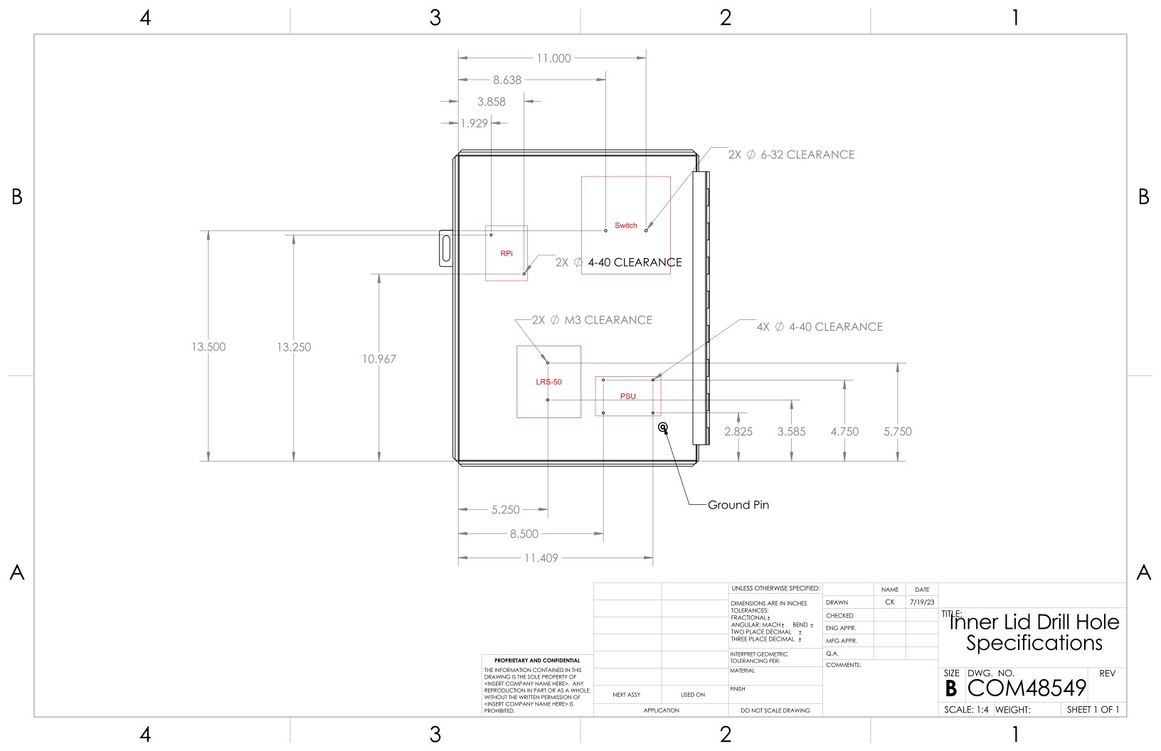 |
For the RPi and PSU, the standoffs are 4-40x1/2" hex. Screws through the boards are 3/16" and screws through the lid are 1/4". The switch is secured by 5/16" screws and is backed with a nut. The LRS-50 uses metric hardware 6mm in length.
Fan
The fan can be attached to the lid with 1/4" L brackets and 4-40 hardware. 5/16" screws from the fan into the threaded side of the L bracket. 3/4" hardware with locking washer + nut combo from L bracket through the lid.
In the case where the SNAP FPGA fan is missing, the large fan is mounted directly to the SNAP board, using the three unused mounting holes on the right hand side. The .stl file for the adjustable height 3D printed bracket can be found here. Use #6 hardware to attach the fan to the base, and #2 hardware to attach the base to the SNAP.
The fan is wired to the Fan terminal of the PSU using the braided red and white wire.
Wiring
| Wiring Diagram |
|---|
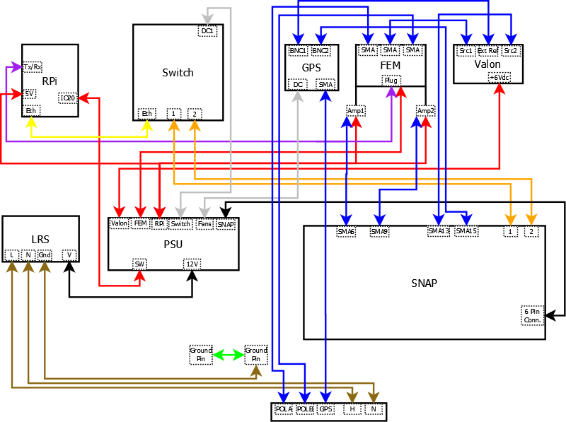 |
Wiring Key
* Valon * Red/white braided wire from +6Vdc to 'Valon' terminal of PSU * 086-3SMR+ cable from Source 1 SMA to top middle FEM * 086-8SMR+ cable from Ext Ref SMA to top left GPS * 086-12SMRSM+ cable from Source 2 SMA to 4th from right SNAP * FEM * 086-24SMRSM+ cable from top left to POL A on interface * 086-24SMRSM+ cable from top right to POL B on interface * 4 port terminal (splice to red/white braided wire) to FEM terminal of PSU * 4 port terminal (splice to blue/green wire) to TXD, RXD terminal of RPi * 086-4 or 086-3SM+ cable from bottom left amp to 6th from left SNAP * Red/white braided wire from bottom left amp to RPi terminal PSU * 086-4 or 086-3SM+ cable from bottom right amp to 9th from left SNAP * Red/white braided wire from bottom right amp to RPi terminal PSU * GPS * 086-15SMRSM+ cable from top right to 2nd from right SNAP * 086-15SMRSM+ cable from bottom SMA to GPS on interface * Power plug to Fan terminal of PSU * SNAP * 18 gauge red/black pair from 6 pin power plug to SNAP terminal of PSU * P1, P2 to SFP+ 1,2 on Switch * Switch * Power plug to Switch terminal of PSU * Ethernet cable from PoE In to bottom left ethernet plug of RPi * LRS-50 * 18 gauge red/black pair from V-, V+ to GND, 12V terminal of PSU * Black, white wire (16 gauge bundle) from L, N to H, N feedthroughs on interface * Green cable (16 gauge bundle) from GND to bottom ground pin * 16 gauge green cable from lid ground pin to bottom ground pin * RPi * Red/white braided wire from 5V, GND terminal to RPi terminal of PSU * Red/white braided wire from IO20, GND terminal to SW, GND of PSUMounting Brackets
Cut the square tube to 15" plus four 1" spacers. Using the 'X' size drill bit, drill out the 10th hole and drill a hole between the 6th and 7th holes from the uncut end. Insert the v-bolt and saddle lock into the drilled holes, fix with washer and nut.
Insert bolts through the third hole in from each end. Add 1" spacer to each, and thread through the tabs on the back of the box. Affix with a washer and nut.
| Mounting Brackets |
|---|
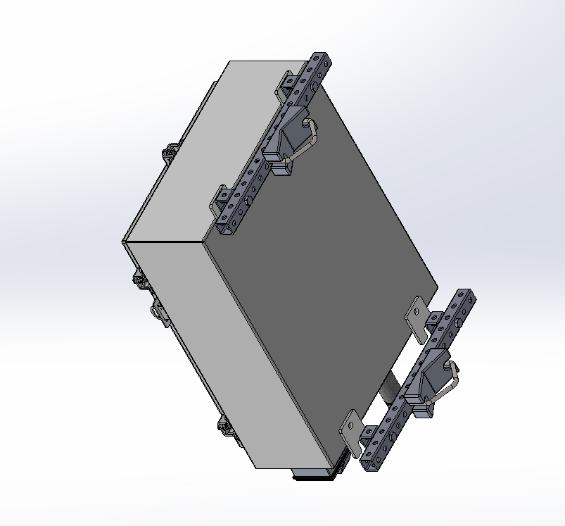 |
Final Steps
Apply lock-tite to all hardware except those with nylocks.
Run fiber cable through the 1 in nipple pipe into the Switch. Plug pipe with steel wool.
Screw feed to the top of the box using 8/32 hex screws and nuts. The LNAs connect to the terminals on the feed, and SMA cables connect the LNA outputs to POLA and POLB on the interface plate. The magnetic GPS unit attaches to a side arm, and screws into the GPS port on the interface plate.
TODO: side arm?
The GReX box is designed to mount on a vertical pipe. Use the V bolt and saddle lock to adjust and tighten.